I Shaped Girders Pdf - H-Beam I-Beam U-Beam Channel Angle Checkered Plate 1. Table 11 Typical offsets curve to chord for single spans Table 12 Typical angular change at a splice between straight girders when there are two splices in.
Top Pdf Fig 1 Cross Sections Of Plate Girders 123dok Com
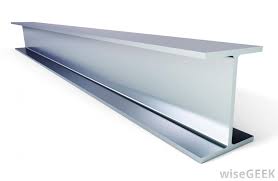
The 1-shape must be adequate for both the negative and positive moment regions.
I shaped girders pdf. Design and load rate the first interior girder Girder B. 7495 cm2 Inertia. 570 plate girder 570 beam w y w y F E t h F E t h Bending M bending moment at the cross section under consideration y perpendicular distance from the neutral plane to the point of interest Ix moment of inertia with respect to the.
Download Full PDF Package. This research aims to develop mathematical models for the optimal design of crane bridge girders by minimizing their weight and thus reducing the operating energy. PGSuper models the various construction stages with Construction Events.
The foundation abutments and piers the superstructure girder truss or arch and the deck. Q235 SS400 of JIS G3192. In this paper results are presented from numerical simulations of a travelling patch load on the flange of I-shaped plate girders of three different dimensions.
8292016 16 Select the W 21 x 62 steel shape to be used for the stringers and click OK. The pretensioned concrete I-girder is the most economical shape for mass production. The FEM modelling aims at simulating the load case of bridge launching over multiple supports.
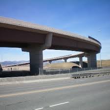
The FEM modelling aims at simulating the load case of bridge launching over multiple supports. I-shaped girder with thick plate. I Shaped Girders A girder bridge in general is a bridge that utilizes girders as the means of supporting the deck.
The number of longitudinal girders depends on the width of the road. The smooth shapes of the girders also provide a sleek appearance as shown in Figure 11. 3 Design Preliminaries.
The steel used in joist girders has a yield strength higher than steel used for shaped or welded beams. I-Shaped Steel Girders Subjected to Bending Moment and Travelling Patch Loading. A girder bridge is very likely the most commonly built and utilized bridge in the world.
Girder Shape Standard AASHT0-1 AASHTOPCI bulb tee and locally developed shapes have been used for spliced girder bridges. Journal of Constructional Steel 2000. The girders have typical bridge girder dimensions and they were subjected to both patch.
The selected steel shape dimensions and properties are copied to the Steel I Shape window as shown below. Figure 5 shows the buckled shape of the L100DS400 model for L cL. Frank and Michael D.
DL is obtained by The U dividing the self-weight of the structure by the total length of the girder system. In each analysis the girder system is subject to a uniformly distributed load UDL applied at the top flange and the buckling load is obtained from the FEA solution. Request PDF System buckling of I-shaped girders The lateral torsional buckling capacity of steel girders is often increased by reducing the unbraced.
Slab 20 to 25cm thick and longitudinal girders spaced from 19 to 25m and cross beams are provided at 3 to 5m interval. Achieved since the trapezoidal shape of the steel girders match the prestressed concrete U-beams that are frequently used in Texas. Its basic design in the most simplified form.
6695 cm2 Inertia. Figure 3-1 shows the assumed construction sequence. Girders can be shaped to follow the varying curvature although the difference from a uniform curve will usually be small.
T-beam bridges are composed of deck. Three girders are normally provided for a two lane road bridge. In this paper results are presented from numerical simulations of a travelling patch load on the flange of I-shaped plate girders of three different dimensions.
2 To perform an analytical analysis of the influ-ence of residual stress on loadcarr- ying capacity for bending of steel I-shaped girders. Since more bridges are being built with continuity over the piers the need for an optimum I-girder section is becoming more important. Request PDF Global Lateral Buckling of I-Shaped Girder Systems A closed form solution for elastic global buckling of twin girder systems interconnected with cross frames is.
Williamson and Karl H. Guidance for erection and construction of curved I-girder bridges inproceedingsStith2010GuidanceFE titleGuidance for erection and construction of curved I-girder bridges authorJason C. Thus the use of curved pre-tensioned concrete I-girders may be potentially more cost effective than the use of curved steel girders and curved post-tensioned concrete girders.
Stith and Andrew Schuh and Jamie Farris and Brian Petruzzi and Todd A. Tub Girders Constant shape Rotated with x-slope Top flange and Web same requirements as I-girder Avoid details more critical than Cat. A bridge consists of three parts.
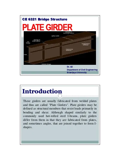
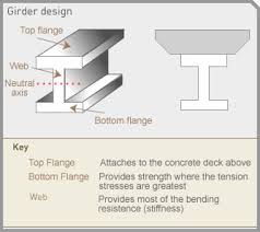
Open web joist girders are lighter than the full web beams of the same. For research objective 1 a thick steel plate is. Design of Plate Girders 91 INTRODUCTION The most common type of plate girder is an I-shaped section built up from two flange plates and one web plate as shown in Figs.
41087033 cm4 170 80 70 20 PC I H-170 Area. GIRDER SHAPE DIMENSION PC - I GIRDER 210 80 70 20 PC I H-210 Area. Helwig and Eric B.
1 To grasp the residual stress distribution in thick steel plates with welding joints. Research objectives are as follows. The girders have typical bridge girder dimensions and they were subjected to both patch.
380 MPa 55 ksi versus 350 MPa 50 ksi. Provided at regular intervals. Q235 SS400 of JIS G3192 H BEAM Standard Grade.
Precast Prestressed Girder Design Example PGSuper Training 242020 4. The difference is the height-thickness ratio tw h of the web. H BEAM Standard Grade.
Bottom Tension Flange ¾ thick wt 80 Classified as fracture-critical for 2-girder spans All bottom flange edges. The design of crane bridge girders requires many revisions to ensure strength and stability and limit the deflection of girders so design aids are needed. Pretensioned concrete girder bridges have not gained popularity in the United States.
In addition since the girders are closed they tend to remain dry and there are fewer places for. A short summary of. FS1 - Girder Floorbeam Stringer Example Last Modified.
31 Construction Sequence. The moment-resisting capacities of plate girders lie somewhere between those of deep standard rolled wide-flange shapes and those of trusses. Below is a link to the file.
I- and H-shaped crane girders with compact. Better cost control for material purchases angles on the Canadian market compared with importing the beam sections. Click OK to save the data to memory and close the window.

Behavior Of Strengthened Composite Prestressed Concrete Girders Under Static And Repeated Loading

Solved The Steel I Shaped Girders Shown In The Figure Are Chegg Com
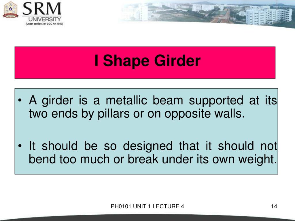
Ppt Ph0101 Unit 1 Lecture 4 Powerpoint Presentation Free Download Id 3923132

Global Lateral Buckling Of I Shaped Girder Systems Journal Of Structural Engineering Vol 134 No 9
I Shaped Girders In Engineering Physics Tech Glads
I Shaped Girders In Engineering Physics Tech Glads
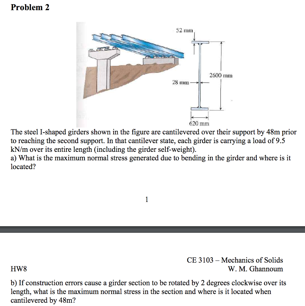
Solved The Steel I Shaped Girders Shown In The Figure Are Chegg Com

The Bridges Models A T Girders Shape Model B I Girder Shape Model Download Scientific Diagram

Cross Section Of I Shaped Concrete Girders For Spans Of 20m 30m And 40m Download Scientific Diagram
I Shaped Girders In Engineering Physics Tech Glads
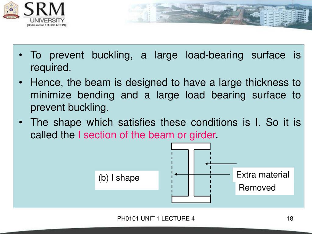
Ppt Ph0101 Unit 1 Lecture 4 Powerpoint Presentation Free Download Id 3923132

Why Girders Are Made I Shaped Youtube

Girder Bridge Wikipedia
Ppt Ph0101 Unit 1 Lecture 4 Powerpoint Presentation Free Download Id 3923132
